Optical metrology is a non-contact, non-destructive measurement technique-. It is precise and it is fast. A structure's width is extracted from its intensity profile in the CCD camera image. The pictures on the right illustrate the principle. The violet rectangle called Region Of Interest (ROI) defines the part of the structure that needs to be measured. In this case the measured width is an averaged width along the line within the ROI. The intensity profile has to be processed extensively to clean it from disturbing effects like statistical photon noise or deformations by optical diffraction effects. This, of course, is done automatically by the MueTec Tools.
How it works
From the image, the intensity profile across the line is calculated and averaged along the line. The resultant intensity profile is second image on the right. Please note that the edges of the profile left and right are not vertical but smeared out resulting in sloping edge profiles. This may be due to optical effects or imperfections in the line shape itself.
The feature size (or critical dimension) is the distance between the left and the right edge.
The CD value with best possible accuracy is calculated from this intensity profile with sub-pixel resolution. The threshold is defined typically between 40% to 60%. of the lowest and the highest intensity found in the intensity profile. The edge position is taken at the intersection of the profile with the threshold, and the resultant (CD) value for the feature size is the distance between both intersections.
For structures in the sub micrometer range below ~0.7µm the MueTec system may use UV illumination (365 nm). In this case the tool is equipped with a special objective lens, a light path and an integrated CCD camera that perform with both white and UV light.
Easy to use
Especially in the field of microelectronics some very special, sophisticated options have been developed to measure structures with a particular layout e.g. very closely arranged lines and spaces, dots and holes on masks, and other memory specific structures.
Although the automated hardware and software package to perform CD metrology is very complex with e.g. the MT3000 it becomes an easy-to-use application. The high precision and performance MueTec achieves in CD metrology is a result of the combination of the highest quality optics, the best laser autofocus system together with our software know-how.The long-standing experience in this complex field, and the capability to combine high precision with individual, customized solutions for all metrology applications, has ensured MueTec a leading position among metrology tool manufacturers.
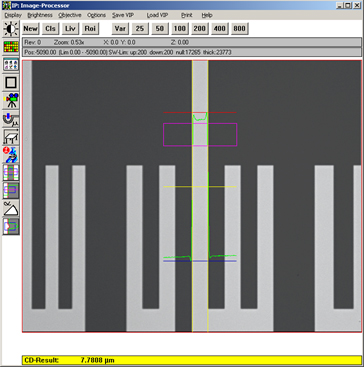
Bright structure with intensity profile (green),Yellow horizontal line: 50% intensity level
Red horizontal line: maximum profile intensity
Blue horizontal line: minimum profile intensity
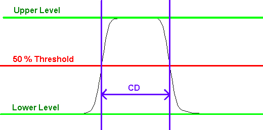
Corresponding scheme of intensity profile
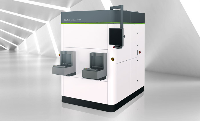
DaVinci 270UV
Mask CD MetrologyShow details
Typical Applications
Critical Dimension Metrology
Features
Cost effective solution for mask layers with feature sizes of 300nm and above
UV and visable light capability
Reflected and transmitted light
Highest quality opticcs
Flexible tool configurations available
CD repeatability (3 sigma) long term < 4 nm (etched layer)
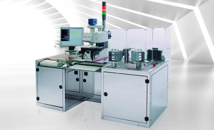
MT3000
Fully automated metrology and inspection system (open cassette)Show details
Typical Applications
CD
Overlay
Film Thickness
Defect Inspection
Defect Review
Features
VIS, UV
Simultaneous wafer handling 75 - 200mm
SECS/GEM
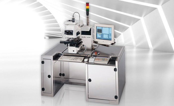
MT2010
Fully automated metrology and inspection system (open cassette)Show details
The MT2010 is designed for high precision defect inspection and metrology tasks on masks up to 6”. The system uses different illumination sources in transmitted and reflected light such as visible, I-line (365nm) and DUV (248nm).
MT2010 comes with laser autofocus and an anti-vibration isolating base frame with light tower.

