

Overlay is the process of aligning one layer of a process stack to the subsequent layer. The overlay error is the shift between those two layers. An overlay specification was created by international SEMATECH to better understand the issues facing optical metrology and to determine the best way to analyze a tool set. The methodologies include: measurement of precision (repeatability and reproducibility), determination of throughput, accuracy, through focus measurement, and Tool-Induced Shift (TIS) variability. The measurement of the overlay is executed at two structures which were produced in different, separate production steps and which in most cases consist of different materials.
Common test structure
A very common test structure to measure the overlay is a box-in-box structure. In preparation for a precise overlay measurement, the software has to recognize or say “learn” the approximate center position and the borders of the inner and the outer box, to define the ideal measurement parameters. This learning procedure is comfortably supported by a single mouse click in the NanoStar software. The result of the learning routine is then displayed in the so called IP Window as shown on the right. Besides box-in-box test structures, the MueTec Tools measures also frame-in-frame, L-bars, circle in circle, cross in cross or any other kind of customized overlay features. Nowadays several other types of structures are in use to measure the overlay parameter.
Advantages of Muetec Systems
The MueTec systems - if equipped with infrared illumination – are able to measure overlay top-to-bottom outside and also inside the substrate.
The overlay application makes it possible to measure wafers with very low contrast appearing in manufacturing processes like STI (shallow trench isolation), and CMP (chemical mechanical polishing) using proprietary algorithms.
A homogeneous objective lens with a Strehl value of better than 0.98, selected especially for overlay demands, guarantees homogeneous images for better performance.
To optimize the overlay measurement performance to its utmost level, tool parameters like illumination homogeneity and optical quality of the objective lenses are automatically corrected. This so called Tool Induced Shift (TIS) of the results is corrected automatically using the automated TIS correction. These parameters for this correction are recorded once by reference measurements on each type of wafer during the job setup and are then automatically used to calculate the corrected overlay results for each measurement.
MueTec has put a lot of effort into resolving these key issues. The outcome is a user friendly, advanced overlay measurement tool with highest precision and throughput, best repeatability and grade of automation and lowest TIS.
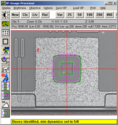
Box-in-box test structure layout
Nowadays several other types of structures are in use to measure the overlay parameter. Below are just two examples:
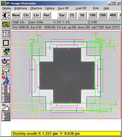
Cross in cross layout
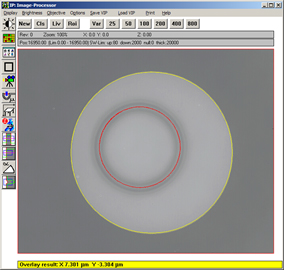
Circle in circle layout
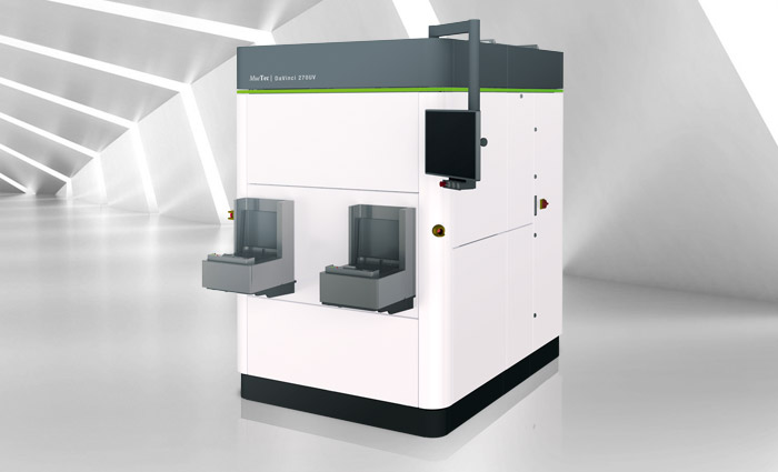
DaVinci 270UV
Mask CD MetrologyShow details
Typical Applications
Critical Dimension Metrology
Features
Cost effective solution for mask layers with feature sizes of 300nm and above
UV and visable light capability
Reflected and transmitted light
Highest quality opticcs
Flexible tool configurations available
CD repeatability (3 sigma) long term < 4 nm (etched layer)
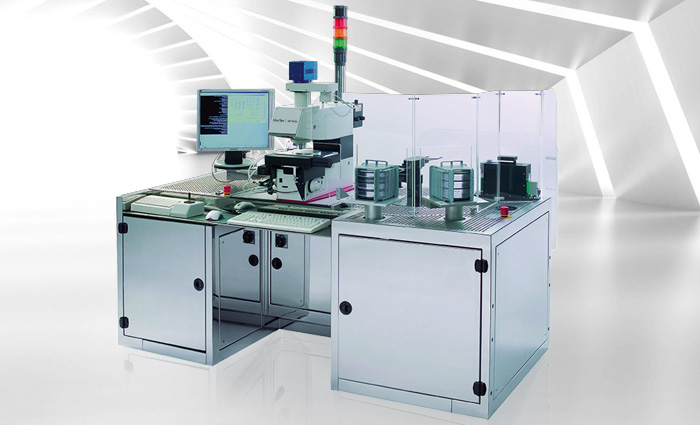
MT3000
Fully automated metrology and inspection system (open cassette)Show details
Typical Applications
CD
Overlay
Film Thickness
Defect Inspection
Defect Review
Features
VIS, UV
Simultaneous wafer handling 75 - 200mm
SECS/GEM
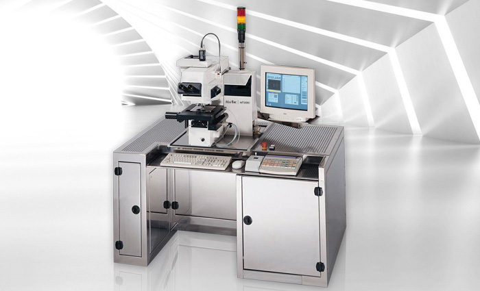
MT2010
Fully automated metrology and inspection system (open cassette)Show details
The MT2010 is designed for high precision defect inspection and metrology tasks on masks up to 6”. The system uses different illumination sources in transmitted and reflected light such as visible, I-line (365nm) and DUV (248nm).
MT2010 comes with laser autofocus and an anti-vibration isolating base frame with light tower.